| UV-VIS-NIR Detector Characterization System | ||
|
|
|
|
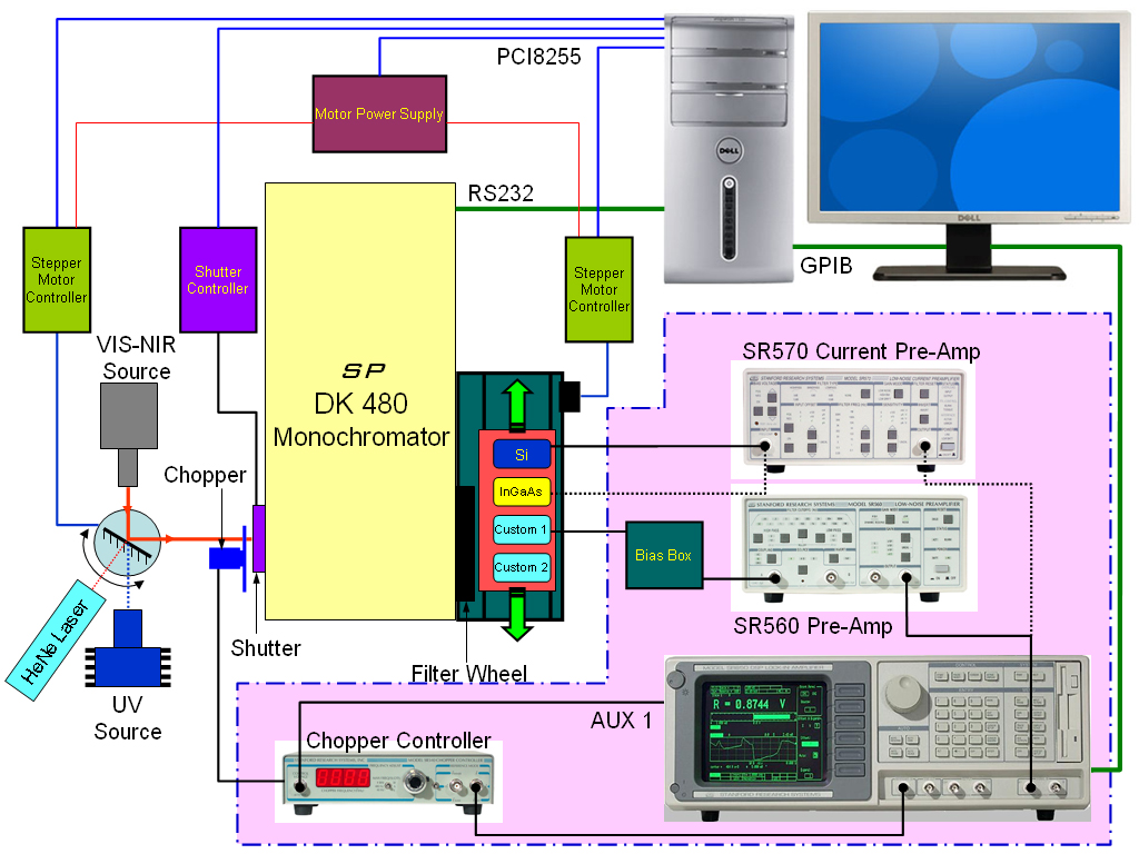
The UV, VIS and NIR detector characterization system is controlled using an in-house software package developed with Microsoft Visual Basic. The heart of this setup is the Spectral Products DK480 monochromator with 3 gratings, a motorized filter wheel, motorized entrance and exit slits. A schematic diagram of the complete setup is shown in Figure B.12. The motorized mirror is used to select the light source: Deuterium UV lamp, tungsten halogen VIS-NIR or HeNe laser. A multi-sample detector stage has two calibrated detectors: UV enhanced Si and InGaAs photodetectors. Another four detector positions are available for custom detector characterization. Software features include automatic output light intensity calibration, real time detector spectral response calculation, auto-align detectors for maximum energy, fully automatic light source, grating and filter selection. The DK480 monochromator and SR850 lock-in amplifier are controled through RS232 and GPIB interfaces, respectively. Mirror and stage stepper motor controllers, shutter, and power unit functions are controlled through the PCI8255 general-purpose PCI board.
Block diagram of the UV-VIS-NIR detector characterization system
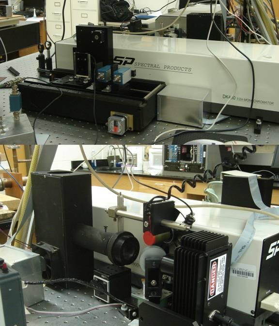
Photograph of the UV-VIS-NIR detector characterization system
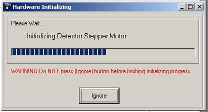
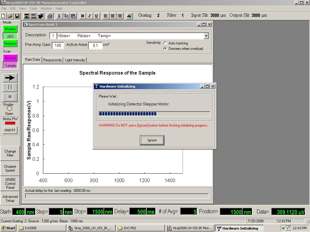
Hardware initialization window. At the starting step of the program, it will search availability of all the instruments and communication status, power up the stepper motor controllers, find the zero position for the stepper motor controlled mirror and sample-stage, and check the shutter status. If successful, this window will automatically disappear, otherwise it shows an error message asking the user to check the status of the particular instrument.
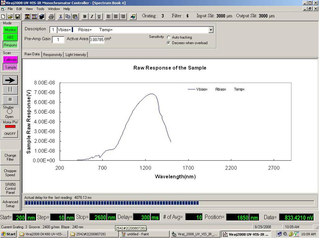
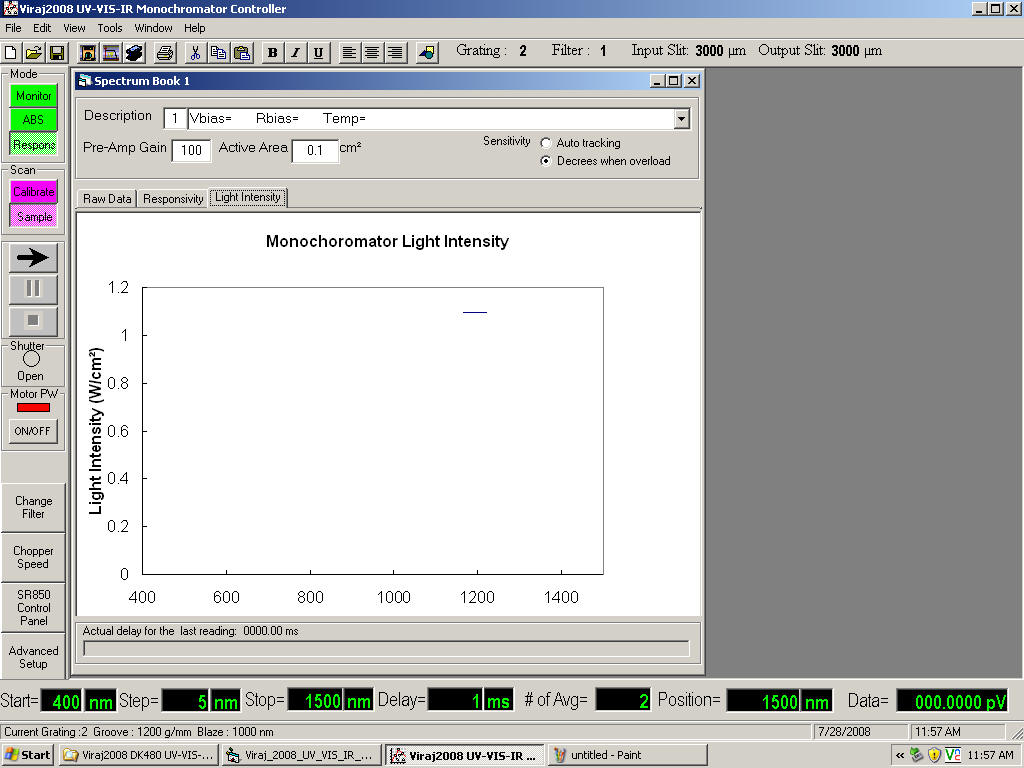
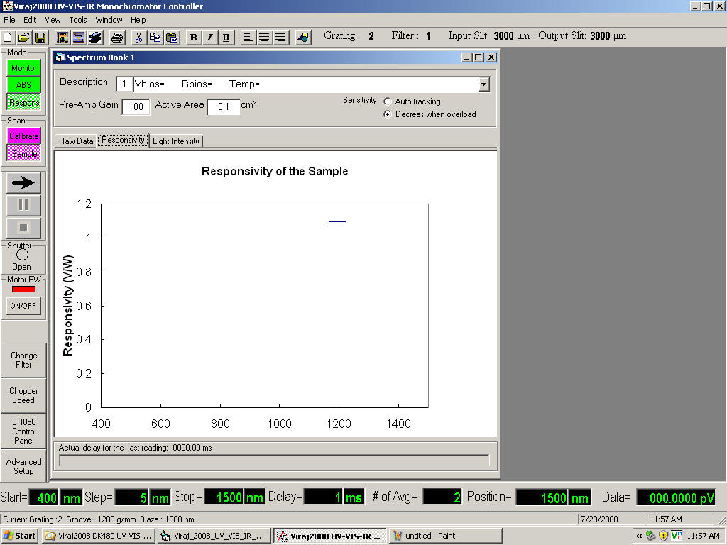
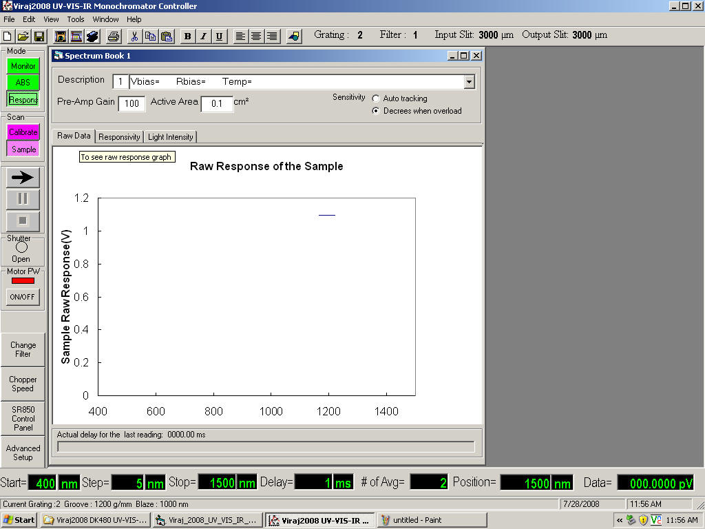
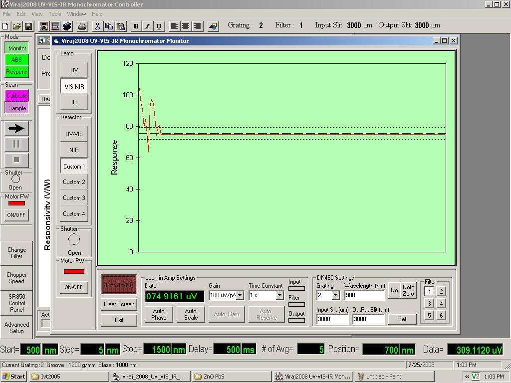
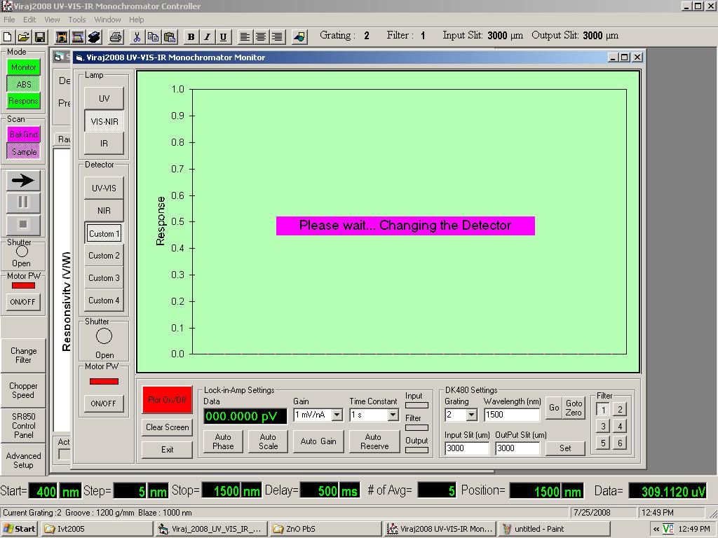
The main user interface of the UV-VIS-NIR detector characterization software. There are three different user selectable working modes: (i) regular spectrometer mode for absorption and reflection measurements, (ii) light intensity calibration mode, and (iii) custom detector characterization mode. The user can observe the real time raw spectrum, responsivity (V/W), and incident light intensity for the custom detectors.
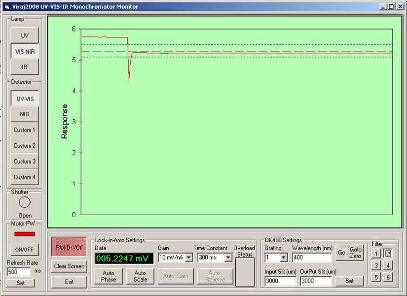
The “monitor-mode” control panel allows the user to control all the instruments, motors and stages manually through the software. The user can change the lock-in-amplifier and monochromator parameters, properly align the detectors, and real time observe the output of the selected detector at a selected wavelength, upon the selection of a light source and a filter.
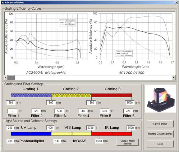
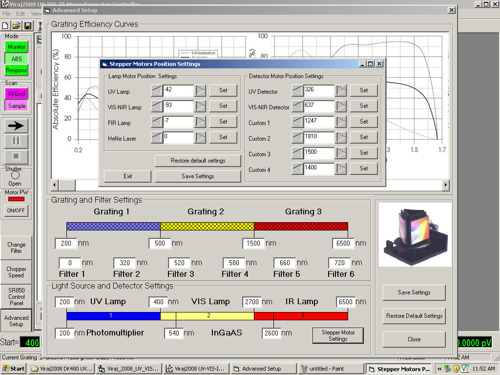
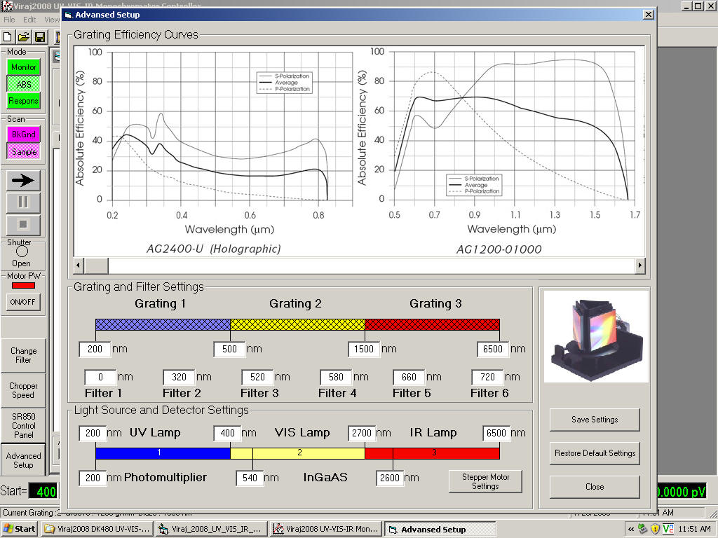
The “Advanced setup” control panel allows the user to change the hardware configurations such as wavelength range for each grating, wavelength position for each filter, wavelength ranges for each light source and the standard detectors (Si and InGaAs). Grating efficiency curves for all available gratings are inserted on the top of the panel so that user can easily determine which grating is most suitable in the wavelength region of interest. Users can save their own configuration settings, and they can also restore the original settings by pressing the “Restore Default Settings” button.
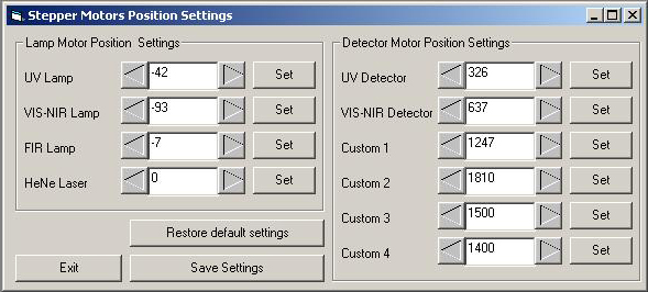
A view of the “stepper motor position settings”. This is another advanced user interface that allows the user to set the light-source-selecting-mirror positions and detector mounting stage positions. The numbers represent the actual number of steps from the zero position of the each stepper- motor. After a hardware modification, such as adding a new sample mount to the custom detector slot, the user can configure the new position and save it for future use.
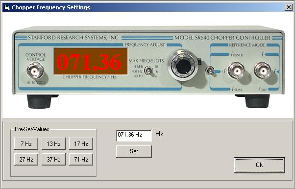
The chopper control panel allows the user to set the chopper frequency to one of the preset values or any other custom value. The user can observe the current frequency on the screen.
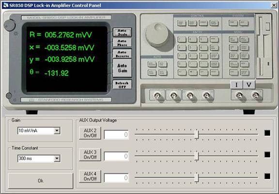
The Lock-in-Amplifier control panel allows the user to change the lock-in amplifier settings and display different components of the output value such as the real part (x), imaginary part (y), phase angle (θ), and magnitude of the output (R). As an optional feature, the user can change the output voltage (-10 V to 10V) of the three auxiliary ports located in the back panel of the lock-in-amplifier.
|
This site was last updated 12/25/08